General Design Philosophy
Pipeline and piping systems shall be designed so that mechanical integrity is maintained under all coincident loading conditions and process temperatures to which these systems can be exposed, and shall represent the most severe anticipated conditions experienced during installation and within the service life of the system.
GRP pipe systems are more sensitive to mechanical overloading, surge, and water hammer effects than steel systems and this requires special care when designing GRP pipe systems.
Jointing System
KTI offers various types of bonded and mechanical joints for GRP piping systems. These tend to be proprietary in nature but can generally be categorized into the following types:
Adhesive-bonded joints
(Conical bell & spigot)
Laminated joints
(Butt & wrap joint)
Mechanical O-ring Joints
(Key – lock joint)
Flanged joints
ANSI/ASME Standards
Threaded joints
High Pressure (API)
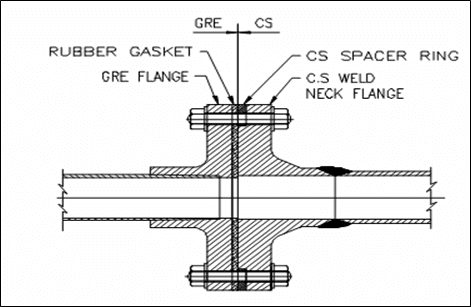
Metallic/GRP interfaces
Hybrid Connections
Adhesive-bonded joints
The adhesive-bonded joint is a rigid type of joint, which consists of a slightly conical (tapered) bell end and a machined tapered spigot end. Adhesive joints have the lowest material cost of all joints, and are structurally efficient when made up correctly.
Make-up of the adhesive joint tends to become more difficult for larger sizes, particularly for pipe above 600 mm diameter. KTI recommends using adhesive bonded joint up to 600 diameter and up to 65 bar design pressure.
Key Components
Key Components
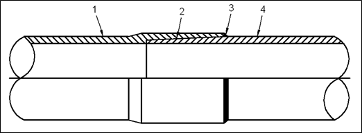
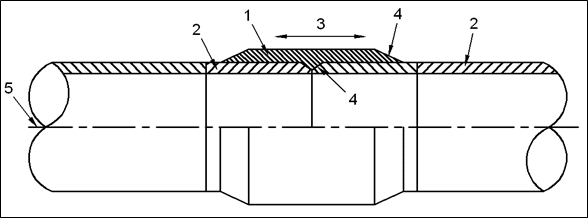
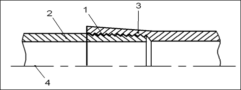
Laminated joints
The laminated joint consists of plain-ended pipe and fittings, prepared, aligned and laminated with reinforcing fibres and resin/hardener mixture as shown in Figure.
There are two types of laminated joint: the outer surface of the pipe can be either lightly abraded leaving a cylindrical surface, or else abraded to provide a taper.
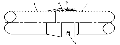
Key-lock joint
Mechanical O-ring elastomeric bell-and-spigot seal lock joints
Elastomeric bell-and-spigot seal lock joints are made up of a spigot end and a socket end with O sealing rings. The socket will be an integrated part of the pipe. If a tensile-resistant joint is required, a locking strip can be incorporated.
These are the simplest joints to assemble, and they can be designed to enable a small amount of axial and angular movement within the joint. They are cheaper and generally structurally more efficient than flanged joints, but more expensive than adhesive joints. They are more bulky than adhesive joints but have the advantage that they can be quickly assembled in poor working conditions and are the preferred joint for concrete gravity-base system piping and ballast transfer piping in ships.
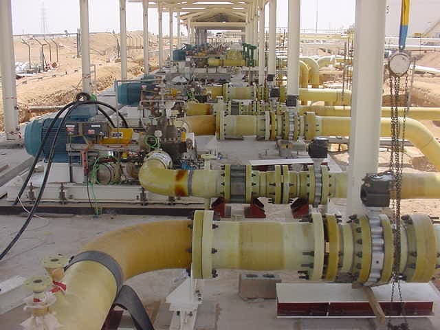
Flanged joints
Flanged joints facilitate connections with steel piping and allow easy assembly and disassembly of piping systems. The outside diameter and hole spacing of flanges should meet the requirements of ASME B16.5/ASME B16.47.
Key Features
Threaded connections
Thread joints are normally used for high pressure piping system. Threaded end connections which conform to API standards should meet the requirements of API 15HR.
KTI recommends using threaded joints for high design pressure (more than 70 bar).
Hydraulic Design
The aim of hydraulic design is to ensure that GRP piping systems are capable of transporting the specified fluid at the specified rate, pressure and temperature throughout their intended service life.
The selection of nominal pipe diameter depends on the internal diameter required to attain the necessary fluid flow consistent with the fluid and hydraulic characteristics of the system.
Fluid velocity, density of fluid, interior surface roughness of pipes and fittings, length of pipes, inside diameter of pipes, as well as resistance from valves and fittings shall be taken into account when estimating pressure losses
The smooth surface of the GRP may result in lower pressure losses compared to metal pipe.
For typical GRP installations, the mean linear velocity for continuous service of liquids is shown in table.
| Fluid Type | Normal Flow (m/s) | Max Intermittent Flow (m/s) |
|---|---|---|
| Liquid | 1 - 5 | 10 |
| Gas | 1 - 10 | 20 |